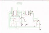
WIP. Just need to connect the pins to the controller port. Y0-Y3 is data out to the PCE. Select and OE/CP are the 2 bit inputs (output from the PCE). I did a quick measurement of the resistors in place, so that's why they're probably ~45k. They're probably 47k resistors, but it makes no difference. They're just pull-up resistors to interface the CMOS I/O logic chips with the cpu.
This is from the actual PCB I have. I don't have a 6 button pad, so I can exactly replicate it via schematic. But I have a very good idea exactly how it works. I'll be over the TAP 6button read code to verify my design, then I'll draw it out and built it from scratch and see how well it functions (four '157s and one '163).
Edit: Didn't fix the the 2button schematic yet, but I worked out a 6button compatible circuit.
6 Button layout:
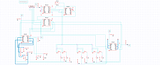
I used a 4th 157 to redirect autofire. The problem is that the TAP does auto Reset (D1). And since you need to re-read the pad again to gain the additional buttons, the counter used for autofire gets clocked twice. So instead of using Q1/Q2, I used Q2/Q3 of the 4bit output. This keeps autofire at the same rates as two button mode. Also, Q0 bit clock is used to select which chip. I still need to see if this is how the original 6button pad does this, or if there there's a bistable input switch on reset instead. The idea is; Reset is asserted to reset the TAP back to port 1, but also outputs to the PAD port 1. This in turns clocks the '163. Like SF2, to read the second set of buttons - the TAP is reset back to port 1 via D1 (reset on/off) - thus the '163 is clocked again and the second set of buttons of the '157 are selected. With the 2button switch, everything is bypassed and used as normal.
I have quick a few junk Genesis pads (really back). They have '157s in them too. So I plan to build out this circuit on the bread board and test it out on SF2 and my own 6button read test code.
 Topic: 2button and 6button gamepad schematic (Read 632 times)